The installation of the boxes is as mentioned in the technical notices (ATec) registered by Fixolite with the CSTB.
Table of Contents
Preparing the boxes
The box must be installed on a sufficiently rigid window.
The box must be installed on a window where the top rail of the frame associated with the box has a deflection of less than 1/150th of the span under the site pressure P1 as defined in document FD P 20-201, without exceeding 15 mm under 800 Pa.
It is assumed that the box does not contribute to the rigidity of the joinery, and that only the frame takes up the wind loads at the top of the joinery.
It is necessary to use the reinforced boxes as soon as the opening exceeds a width of 1.6 m. For reinforced boxes, the width of the opening must be a maximum of 4.5 m.
The joinery closing the box must be designed to allow access to the roller shutter mechanisms and removal of the roller.
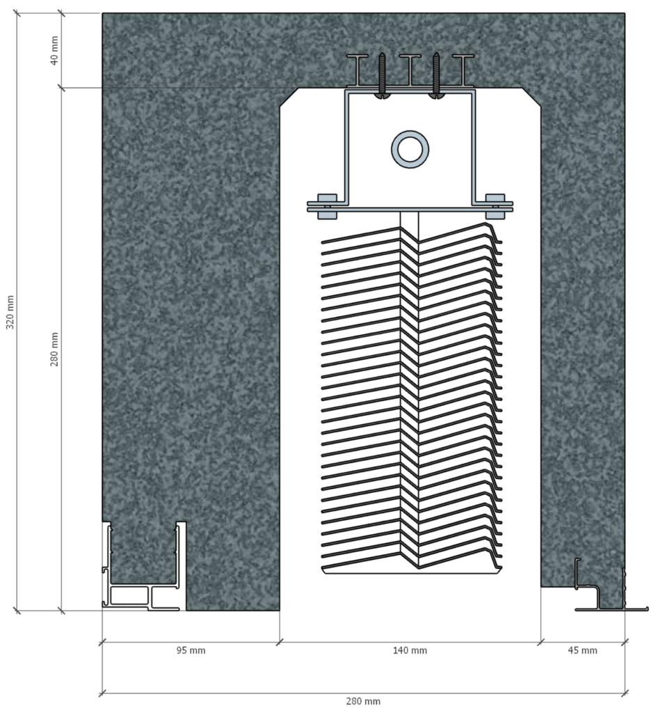
Normally, the boxes are delivered to length and fitted with side cheeks. The box is twice as long as the heel of the side panels - i.e. 190 mm (2 x 95) or 130 mm (2 x 65) depending on the type of side panel - as the width of the finished opening (with finishing plaster).
Once the box has been cut to size, the assembler mounts the cheeks on the ends of the box:
1. Spread the wings of the boot apart using a spacer.
2. Integrate the cheek into the box to compress the joint
3. Remove the spacer and tighten the walls so that the cheek can be clipped into the inner and outer profiles.
For the Venetian Blind boxes, once the box has been cut to length, the polystyrene sides are fixed with silicone adhesive or single-component polyurethane adhesive.
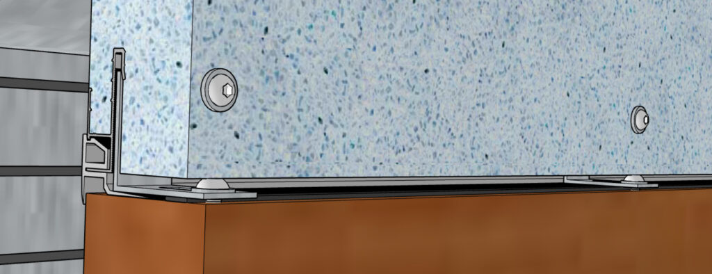
The cement mortar on which the casing is laid provides a watertight seal under the cheek. A support bracket is screwed into the profile every 70 cm with 2 screws 30 mm apart.
At this stage of production, the box can be delivered to the building site.
Installation method
Once the jambs have been assembled to the required level, the mason prepares the base of the casing with a bed of mortar. If necessary, in the case of thick insulation, additional insulation is glued to the face of the casing using polystyrene adhesive.
Installation during structural work
ITI vs ITE
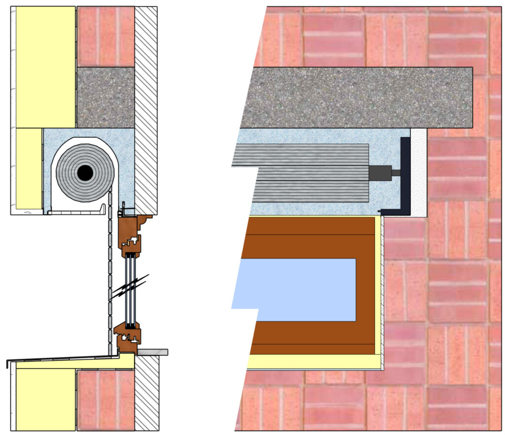
For insulation from the inside (ITI), the outer flange of the box should be aligned with the outer wall:
For external insulation (ITE), the inside flange of the casing should be aligned with the inside wall:
Trunk alignment
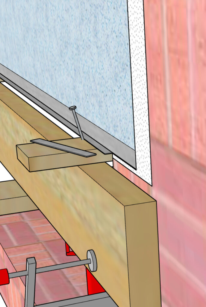
- Whichever method is used, the sides of the box must be braced and held in alignment by nails or battens during installation.
- The boxes must be level and plumb.
- The shell is secured to the structure by filling the recesses when the lintel and/or floor are poured. To fill the recesses properly, the concrete must be fine-grained (< 10 mm).
- The end cheeks that transmit the roller shutter loads to the shell must rest on hard, flat surfaces that are perfectly level.
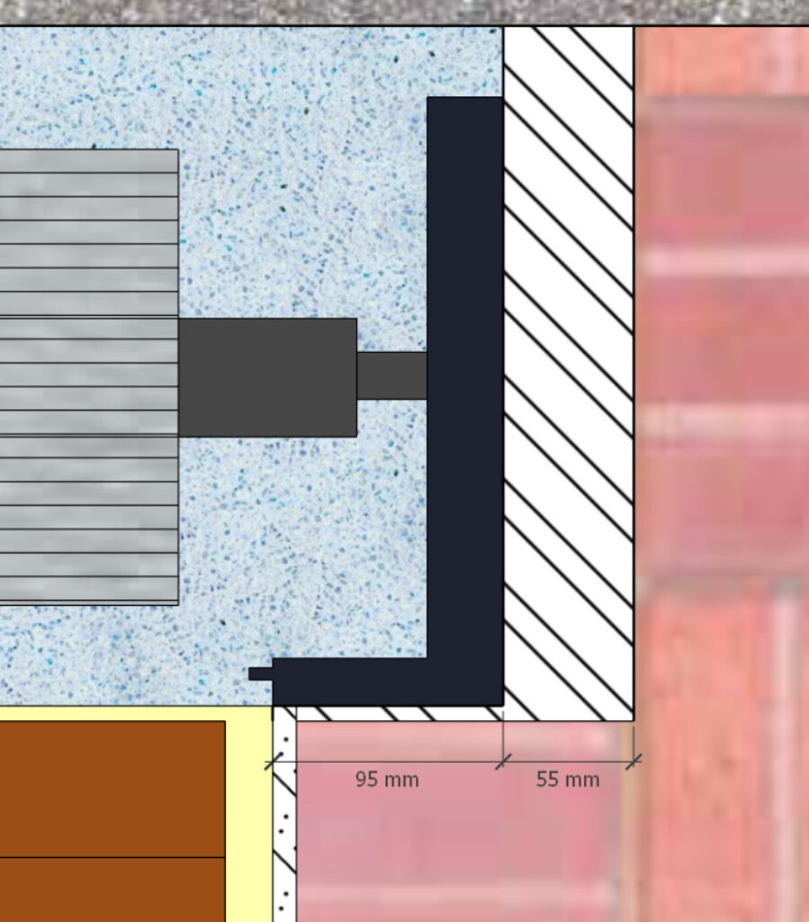
- The edge of the heel of the cheek must be aligned with the finishing plaster (the length of the box must take account of the heel of the cheeks and the finishing plaster).
- A gap of 5 to 15 mm must be left between the box and the frame of the joinery.
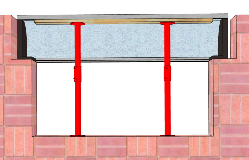
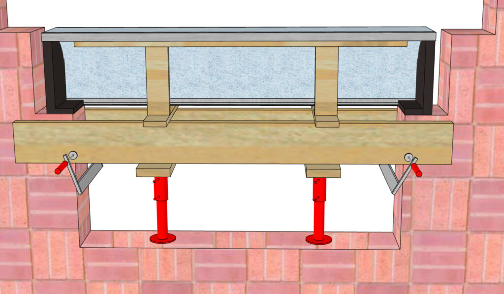
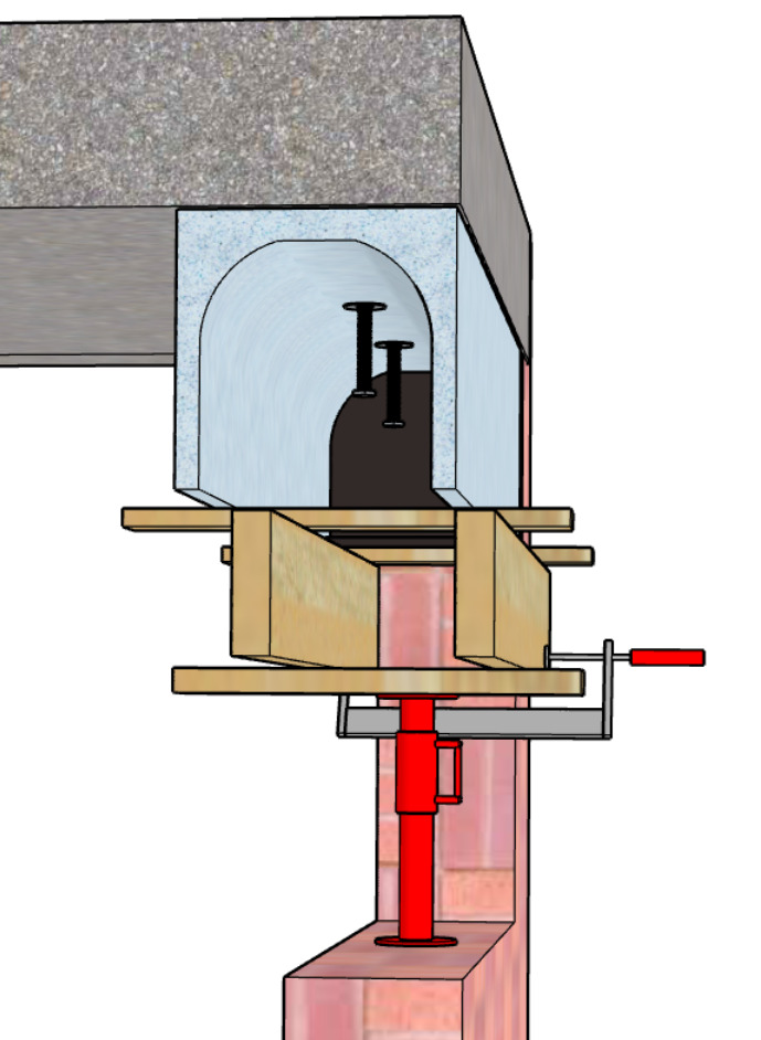
Shoring before formwork and lintel pouring
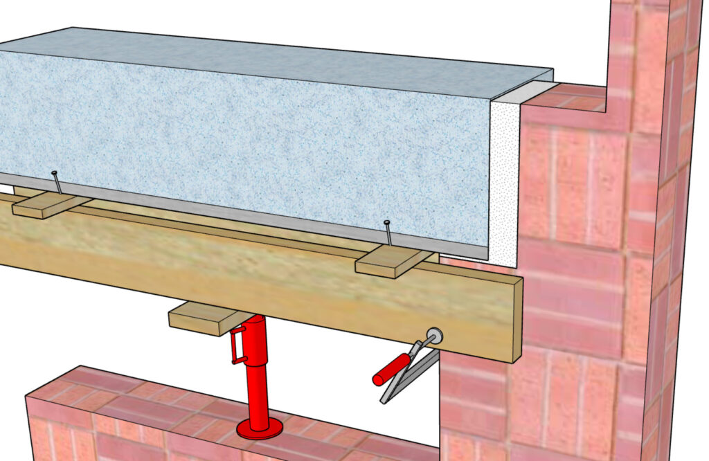
Two battens are positioned under the box and held in place by two clamps. Crosspieces are positioned on these battens with a maximum centre-to-centre distance of 60 cm. One crossbar is positioned close to the cheek to avoid stressing the cheek.
The shoring is then done under the bastaings every 60 cm.
The lintel formwork is in place and the props can be removed 28 days after the concrete has been poured.
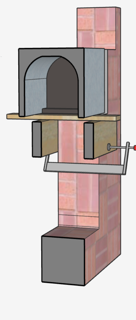
Half-lintel case for bay window
For the half-lintel boxes under 1.60 m of bay width, a 8 cm wide x 4 cm high stringer is positioned under the upper horizontal part of the half-lintel box and supported by props 60 cm apart.
For the half-lintel boxes over 1.60 m bay width :
- Two support stringers are clamped to each side of the wall and supported by props 60 cm apart.
- Support battens are placed perpendicularly on the longitudinal members every 60 cm.
- A wooden strip with a cross-section of 6 x 6 cm is fixed vertically to the latter.
- A side rail 8 cm wide x 4 cm high is positioned under the upper horizontal part of the box and supported by battens 60 cm apart.
Joining boxes to masonry
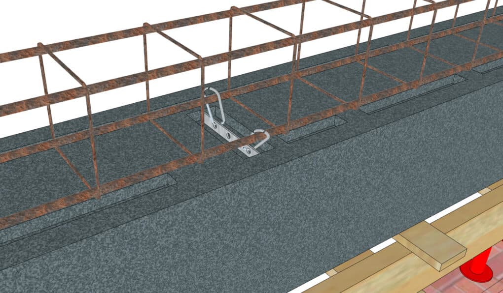
Reinforced boxes
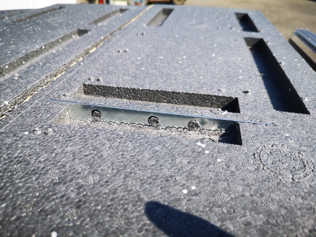
For the reinforced boxes (panel > 1.6m), the reinforcement brackets are positioned in the mould before the polystyrene is injected. The brackets are exposed at the top so that they can be connected to the wall ties. The connection between the reinforcement and the wall ties is made by a tie (galvanised wire with a minimum diameter of 2.5 mm). A minimum of two ties must connect each of the angle brackets.
Non-reinforced boxes
For the non-reinforced boxesThe connection is made when the concrete is poured into the recesses at the top of the box. It is also possible to attach the reinforcing mesh to the wall ties by digging slightly into the polystyrene.
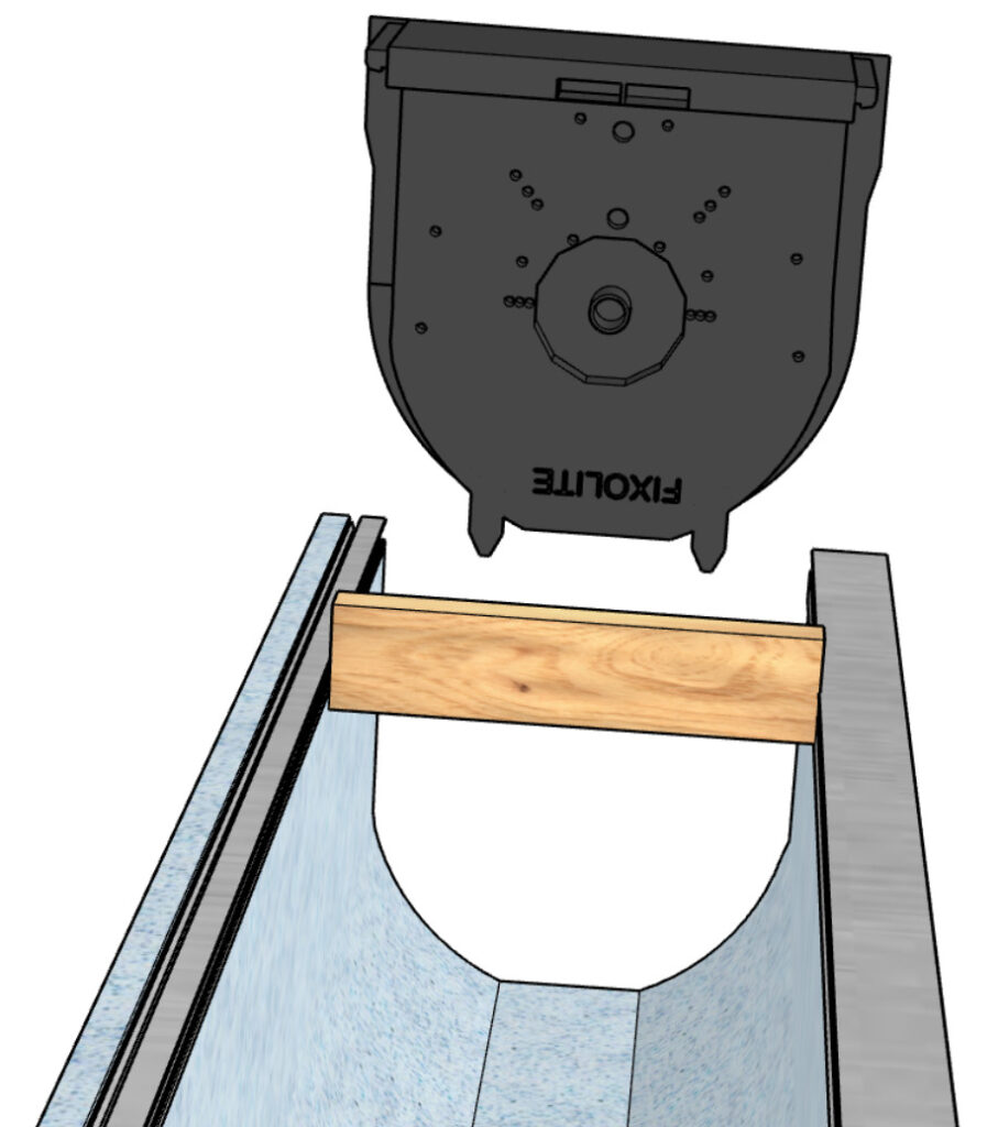
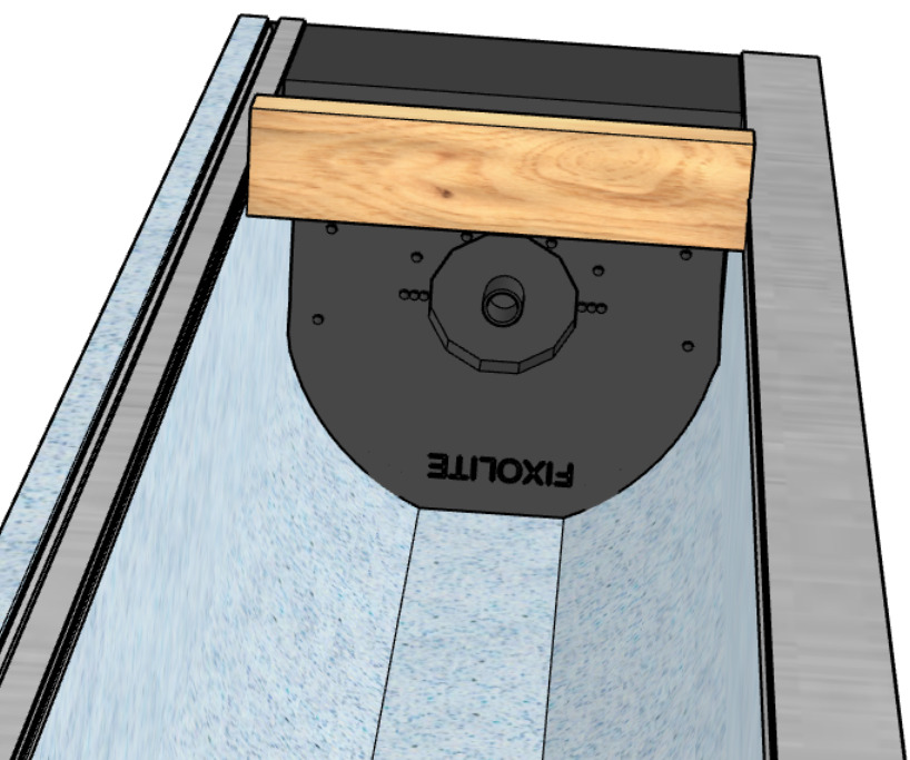
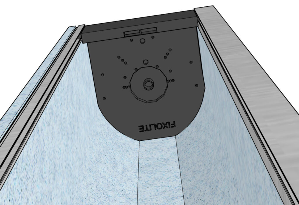
Under-slab installation / renovation
This type of installation is mainly used when the shell of the building is constructed using industrialised techniques, or in the case of renovation work.
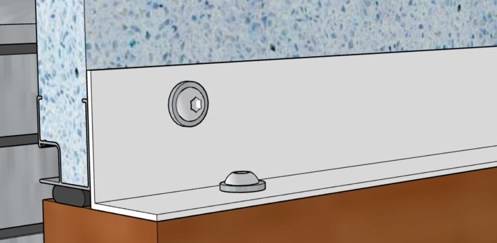
The caisson is fixed to the concrete by means of 8 mm galvanised lag bolts - with 50 mm washers - (standard NFA 91-121), positioned at the bottom of the shell, spaced out every 60 to 80 cm and screwed into dowels placed in the concrete.
A bonding product, applied beforehand to the top of the casing, completes the fixing and ensures a watertight seal with the shell. This product (adhesive mortar) is chosen from those used in external insulation systems (polystyrene/concrete) which have a valid Technical Approval.
Earthquake-resistant treatment
In accordance with current regulations, it is possible to reinforce openings fitted with lintel boxes. The diameters, number and locations of the reinforcing bars will be defined by a concrete study.
Exterior cladding
In the case of internal thermal insulation (ITI), the outer flange of the casing is systematically covered with a continuous layer of 3 to 5 mm thick gobetis mortar. To do this, the casing must be set back 3 to 5 mm from the outside wall.
For polystyrene-finished boxes, apply a primer beforehand.
Coatings are applied to a dry substrate. In the case of facing bricks, do not exceed a total weight of 30 kg/m².
It is advisable to check beforehand that the faces of the aluminium profile have been notched in line with the jambs (applies to the external side for installation with internal insulation).
These renderings must incorporate a fibreglass reinforcing mesh (or one with anti-corrosion treatment) that complies with standard NF DTU 26.1. This reinforcement must not be applied to the substrate, but must be incorporated into the rendering and must cover the entire casing, extending at least 15 cm beyond the masonry.
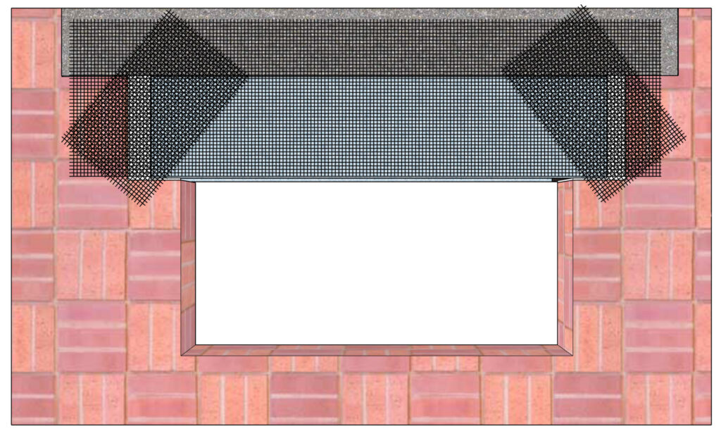
A corner reinforcement strip measuring at least 50 x 30 cm is positioned diagonally at each end of the box.
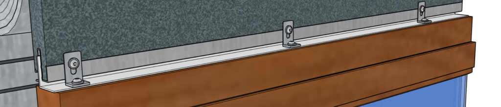
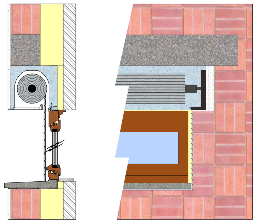
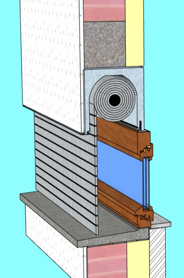
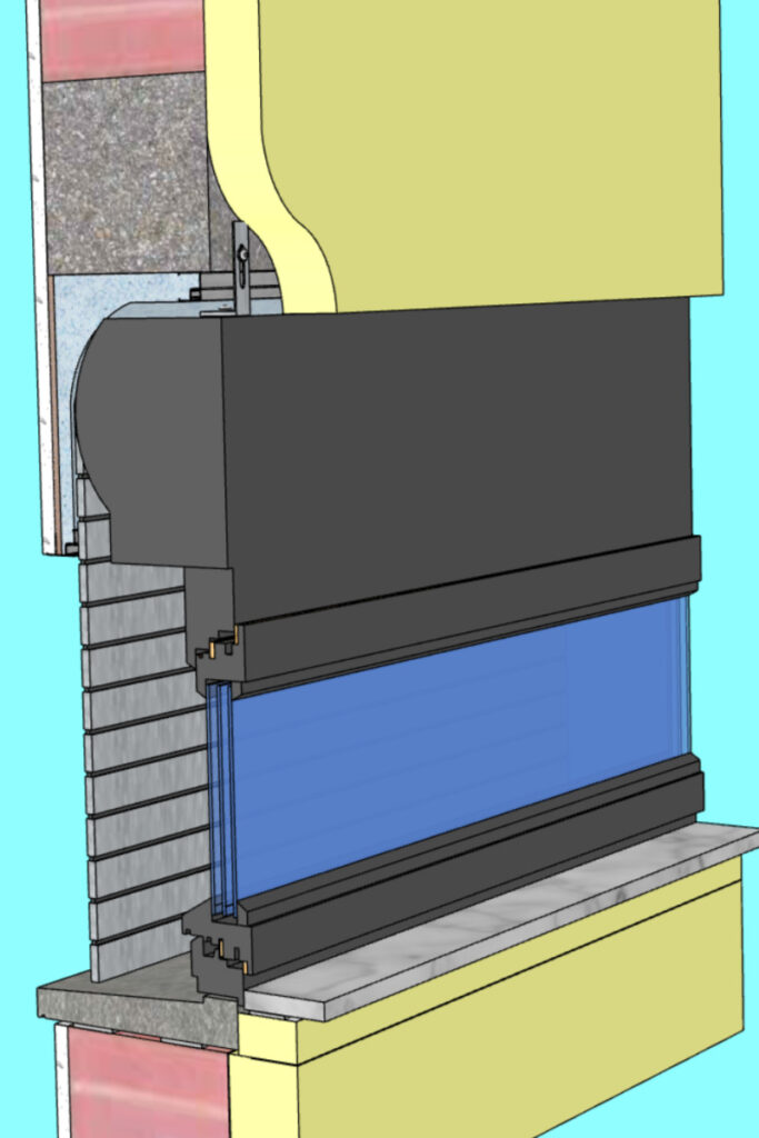
Connecting joinery
Here are some examples of connections to the frame.
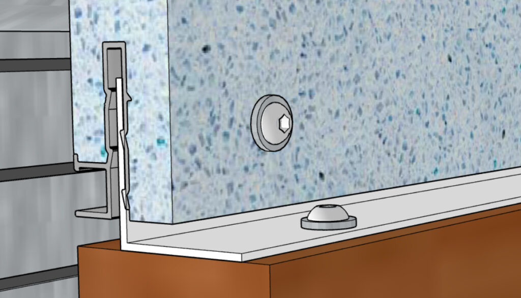
8H rail
Fixed with PVC angle and screws. A foam or EPDM seal can be fitted under the rail.
8R rail
Fixed with PVC angle and screws. A foam or EPDM seal can be fitted under the rail.
8E rail
Fixed with J8 seal (external winding), brackets and screws.
For reinforced boxes, a connecting bracket is positioned with a maximum centre-to-centre distance of 40 cm :